Home · News · Industry News · From Glass Blank to Optical Component: Inside the Optics Manufacturing Process
From Glass Blank to Optical Component: Inside the Optics Manufacturing Process
Author: AdminDate: Oct 14,2026
If you have ever received a batch of optical filters where the transmission curve shifts by a few nanometers from the previous order, you know the frustration. The design was identical, the drawing was clear, yet the parts behave differently. In most cases, the root cause is not the design—it is how the optics manufacturing process was executed. This article breaks down the core stages of producing optical components, from glass blank selection to final inspection, and highlights the tolerances and purchasing points that separate a smooth project from costly rework.
The most consistent optical components come from suppliers who control material properties and process windows at every step, rather than relying on final inspection to catch problems. Understanding what happens on the factory floor helps you ask better questions, compare quotes fairly, and avoid the hidden costs of re-polishing, re-coating, or scrap.
When you specify an optical filter, you are not just choosing a coating or a dye—you are choosing a glass substrate. The substrate's internal quality determines how well the final part will perform, especially in applications where transmitted wavefront or spectral stability matters. Colorless optical glass such as B270, K9/BK7, or fused quartz is common for filters and windows. Each has trade-offs: B270 offers good transmission from the visible to near-IR but has a lower softening point; quartz withstands harsh environments but costs more.
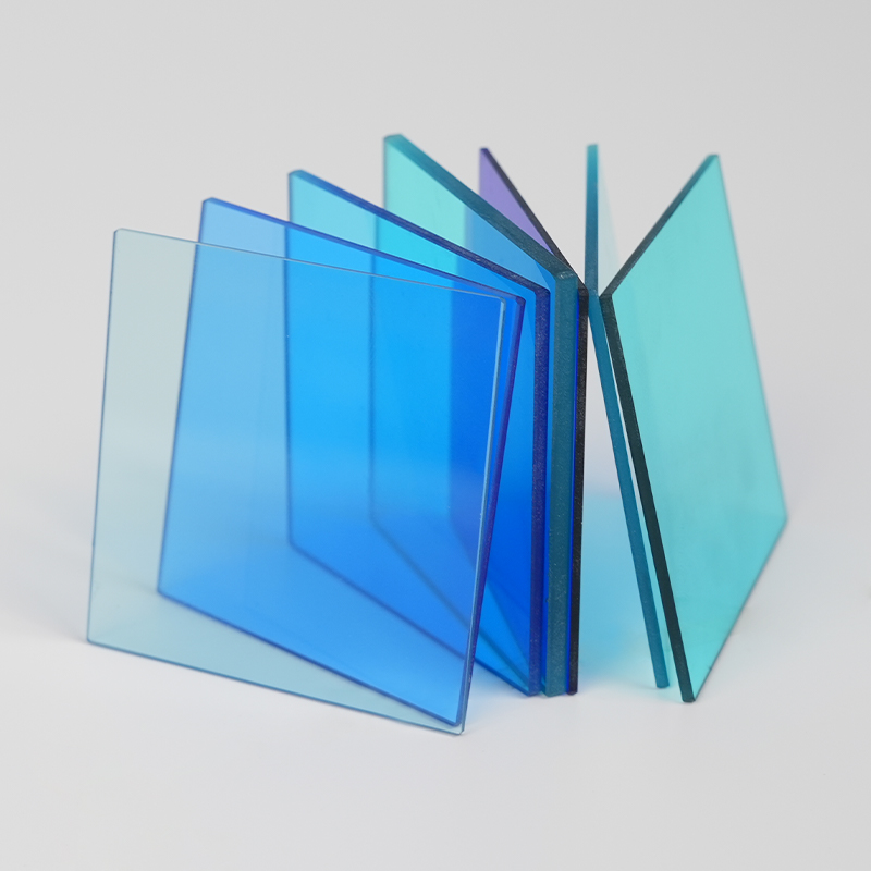
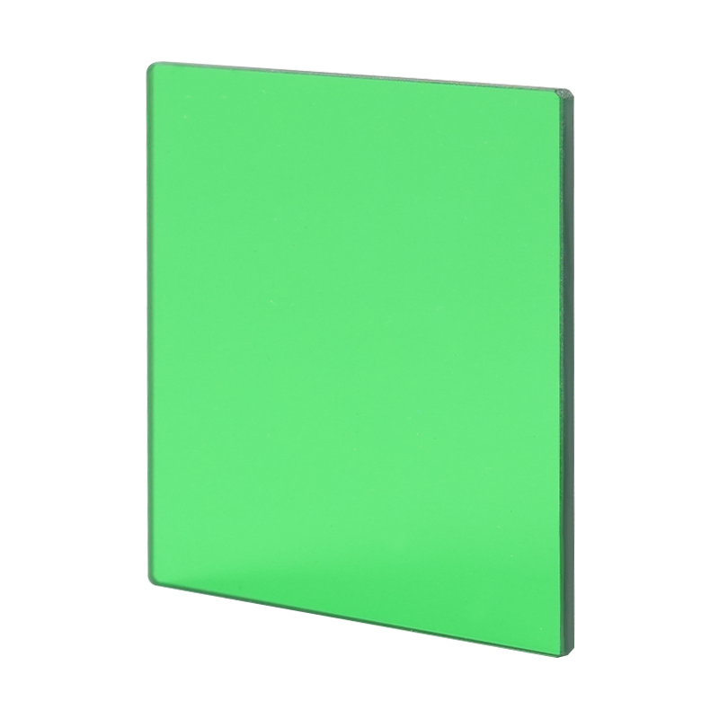
For colored glass filters, the material itself absorbs specific wavelengths, so the melt consistency directly affects the spectral curve. Nantong Xiangyang Optical Element, for example, produces over one hundred types of colored optical glass covering UV, visible, near-infrared, and infrared regions. That breadth matters because a supplier who understands glass chemistry can recommend a substrate that matches your optical density and thickness requirements without forcing a compromise. Before you approve a quote, ask for the glass batch's transmission data, not just a typical curve from a catalog.
Table 1: Comparison of common optical glass substrates.
From Blank to Shape: Cutting, Grinding, and Generating
Once the glass type is fixed, the blank must be shaped. For a simple window or filter, this often means cutting a larger sheet into squares or rounds, then grinding the edges and faces to the target thickness. The first material-removal step, sometimes called generating or rough grinding, uses loose abrasives—typically silicon carbide or alumina with grit sizes from 60 to 220 mesh. This stage removes saw marks and establishes the basic geometry, but it leaves a rough, opaque surface with subsurface damage.
The depth of that damage matters: if it extends too deep, subsequent polishing will take longer and may not fully remove it. Industry guidelines suggest removing at least two to three times the damage depth in the following fine grinding step. A common mistake buyers make is focusing only on final surface roughness while ignoring the subsurface damage introduced earlier. That damage can cause haze, reduced transmission, or even delayed cracking under thermal cycling. A well-controlled optics manufacturing process tracks abrasive size, lap pressure, and cycle time for each step. According to general optical fabrication references, rough grinding typically produces surface roughness (Ra) in the 1–2 µm range, fine grinding brings it to 0.1–0.5 µm, and polishing is needed to reach below 1 nm. The chart below illustrates this progression.
Subsurface damage is invisible to the eye but shows up later as scattered light or a failed laser damage test. If your supplier skips a fine grinding stage or rushes it, the polishing step will either take too long or leave pits that reduce yield. Ask what abrasive sizes they use between rough and fine grinding, and whether they verify damage removal with a microscope or etch test.
Polishing: Where Surface Quality Is Won or Lost
Polishing removes the remaining subsurface damage and produces a transparent, specular surface. For most optical glass, a slurry of cerium oxide or zirconium oxide on a polyurethane pad works well. The goal is not just low roughness but also a surface free of scratches and digs that scatter light. The scratch/dig standard (often MIL-PRF-13830B) defines acceptable cosmetic defects: a 60-40 scratch-dig, for instance, allows scratches up to 60 µm wide and digs up to 0.4 mm diameter. For imaging or laser applications, you may need 20-10 or even 10-5.
The polishing step also influences transmitted wavefront error (TWFE). A poorly controlled polish can introduce edge roll-off or mid-spatial frequency errors that distort the wavefront. If your application involves coherent light, specify TWFE in waves at 632.8 nm. For a 25 mm diameter filter, a typical commercial tolerance might be λ/4, while precision optics can reach λ/10. Ask your supplier how they measure it—an interferometer with a proper transmission sphere is the norm. Nantong Xiangyang’s facility includes high-end optical processing and testing equipment, and their quality system follows ISO9001-2000, which provides a baseline for repeatability. You can read more about their quality approach on their quality requirements page.
Another practical point: edge chips. Even a perfect polished face can be rejected if the edge has chips larger than the drawing allows. Suppliers who chamfer or edge-grind after polishing reduce the risk of chipping during handling and assembly. Specify your edge chip tolerance clearly—many catalogs assume 0.5 mm, but precision applications may need 0.1 mm or less.
Coating, Silk-Screen Printing, and Tempering: Adding Function
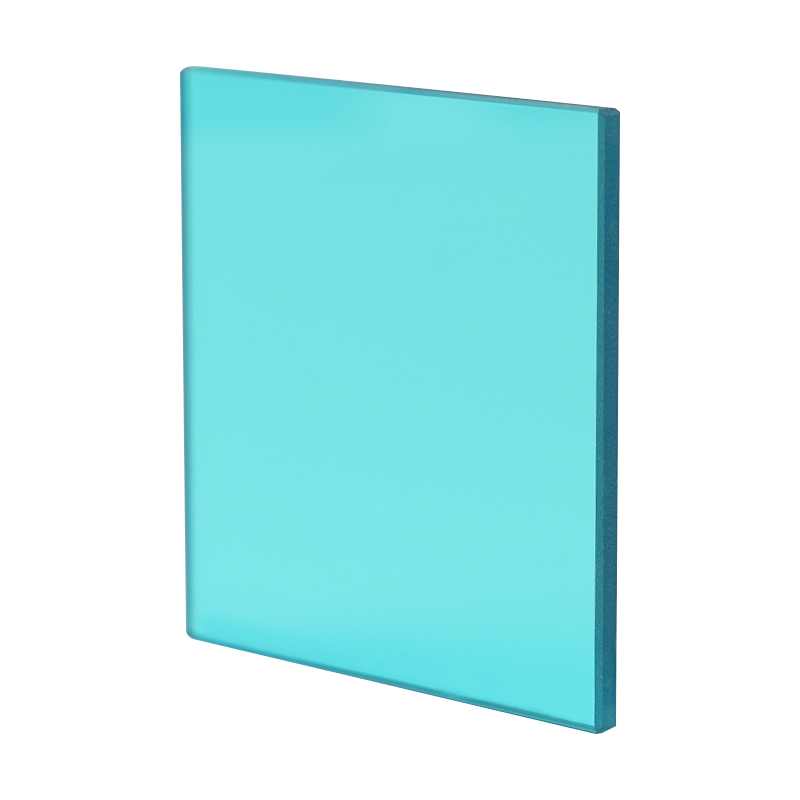
After polishing, many optical components receive additional layers. Thin-film coatings can create anti-reflection, high-reflection, or bandpass filters. But for some applications, an absorbing glass filter is more robust and cost-effective than a coated filter, especially when you need to block a broad band or handle high power. Selective absorption glass filters, for example, absorb specific wavelengths through the glass body rather than surface interference. That makes them less sensitive to angle of incidence and less prone to laser damage. If your project involves UV blocking, a cut-off glass filter like a UV cut-off filter can provide sharp transition and high blocking.
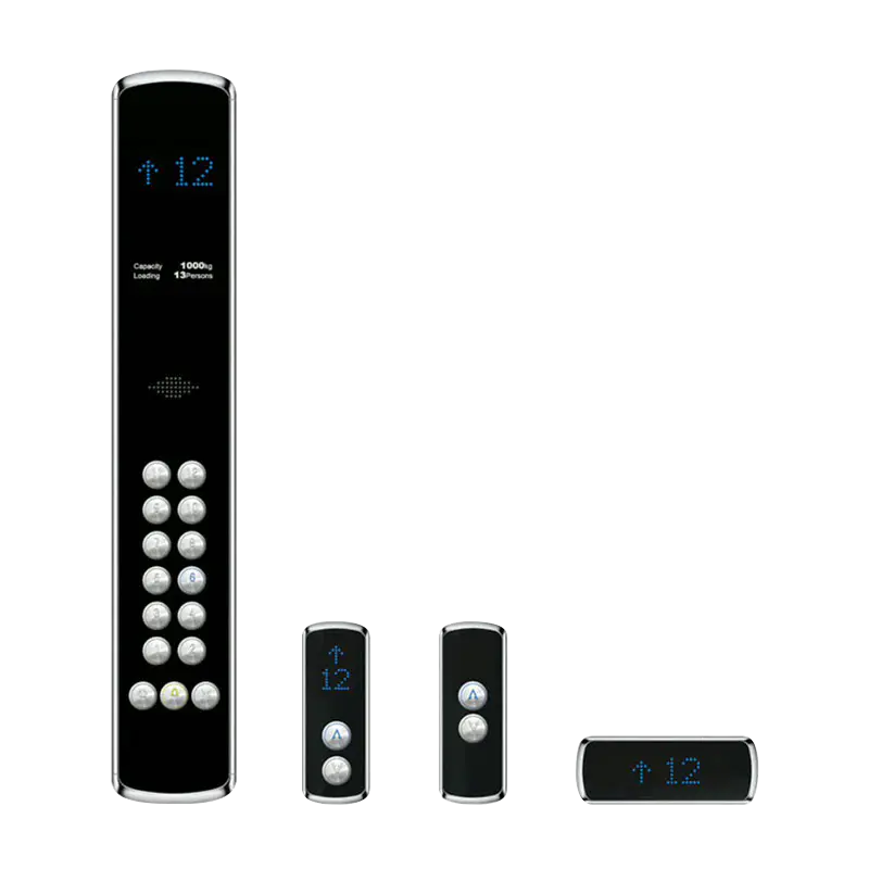
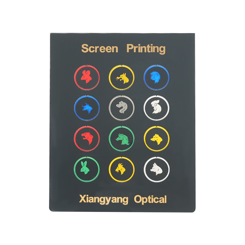
For elevator or appliance panels, the process shifts to silk-screen printing and tempering: printing a colored pattern on glass, drying, then heating to around 600–700°C to fuse the ink and strengthen the glass. Tempered glass panels resist impact and thermal stress, which is why they appear in elevator control panels and appliance interfaces. The key here is ink adhesion and color consistency—a poor print can fade or peel. Buyers should ask for adhesion tests (e.g., tape test per ASTM D3359) and hardness checks. Nantong Xiangyang also produces tempered glass silk-screen printing for elevator panels, appliance panels, and instrument displays, which shows their process covers both optical and architectural glass. You can see their broader factory capabilities for more context.
Inspection and Metrology: What Buyers Should Ask For
Final inspection is where you verify that the process worked. For optical filters, spectrophotometry gives the transmission curve across wavelengths. For windows and lenses, interferometry measures surface figure and transmitted wavefront. Surface roughness is checked with a profilometer or atomic force microscope. A reliable supplier will provide actual measured data for the batch, not just a typical curve.
When reviewing a quote, ask these questions: What is the batch-to-batch tolerance on center wavelength? What scratch/dig standard do you guarantee? How do you handle edge chips? What is the maximum subsurface damage you allow before polishing? If the answers are vague, you may be buying a part that works in the lab but fails in production. Also consider the total cost of ownership: a slightly more expensive filter with tight tolerances can save hours of alignment and reduce scrap. Nantong Xiangyang offers customization and can process various brands and specifications of filter glass, which helps when you need a specific optical density or thickness.
For critical projects, request a first article inspection (FAI) report with measured transmission, wavefront, and surface quality data. That report becomes your baseline for accepting production lots. Without it, you have no objective way to judge whether batch 5 matches batch 1.
Frequently Asked Questions
Q1: What is the optics manufacturing process?
It starts with glass blank selection, then cutting, grinding, polishing, optional coating or silk-screen printing, and final inspection. Each step controls different properties like geometry, surface quality, and spectral performance.
Q2: How long does optical glass manufacturing take?
For standard filters and windows, typical lead times range from 2 to 4 weeks after drawing approval. Custom glass melts or complex coatings may take 6 to 8 weeks. Ask your supplier for a process schedule based on your quantity.
Q3: What is the difference between optical glass and regular glass?
Optical glass has controlled refractive index, low bubble and striae content, and tighter tolerances on thickness and parallelism. Regular glass focuses on mechanical strength and clarity, not wavefront or spectral consistency.
Q4: Can you manufacture custom optical filters?
Yes. Custom filter production usually involves selecting a colored glass melt or designing a thin-film stack, then grinding, polishing, and dicing to size. Provide your target transmission curve, blocking range, and dimensions.
Q5: What should I check in an optical filter datasheet?
Look for center wavelength, bandwidth (FWHM), peak transmission, blocking range, surface quality (scratch/dig), thickness tolerance, and transmitted wavefront error. If any of these are missing, request measured data.
Q6: How do you ensure batch consistency in optics manufacturing?
Batch consistency comes from controlling raw glass properties, abrasive and slurry specifications, machine settings, and inspection frequency. Suppliers who track process parameters and retain samples from each batch can usually maintain tighter consistency.




 English
 Español